The Well Design module
One workspace, one data model, from spud to end of well
Well planning, positional integrity, drilling engineering and execution reporting in a single module. Every page shares the same project selection, set once and carried through planning, engineering, execution and reporting.
- Built for
- Drilling contractors, directional companies and operator drilling teams
- Validated against
- Professional directional plans and measured field data
- Every result carries
- The engine version and the warnings it was produced with
How it works
One workspace, from spud to end of well
- Workspace Each job a project, with its wells and wellbores.
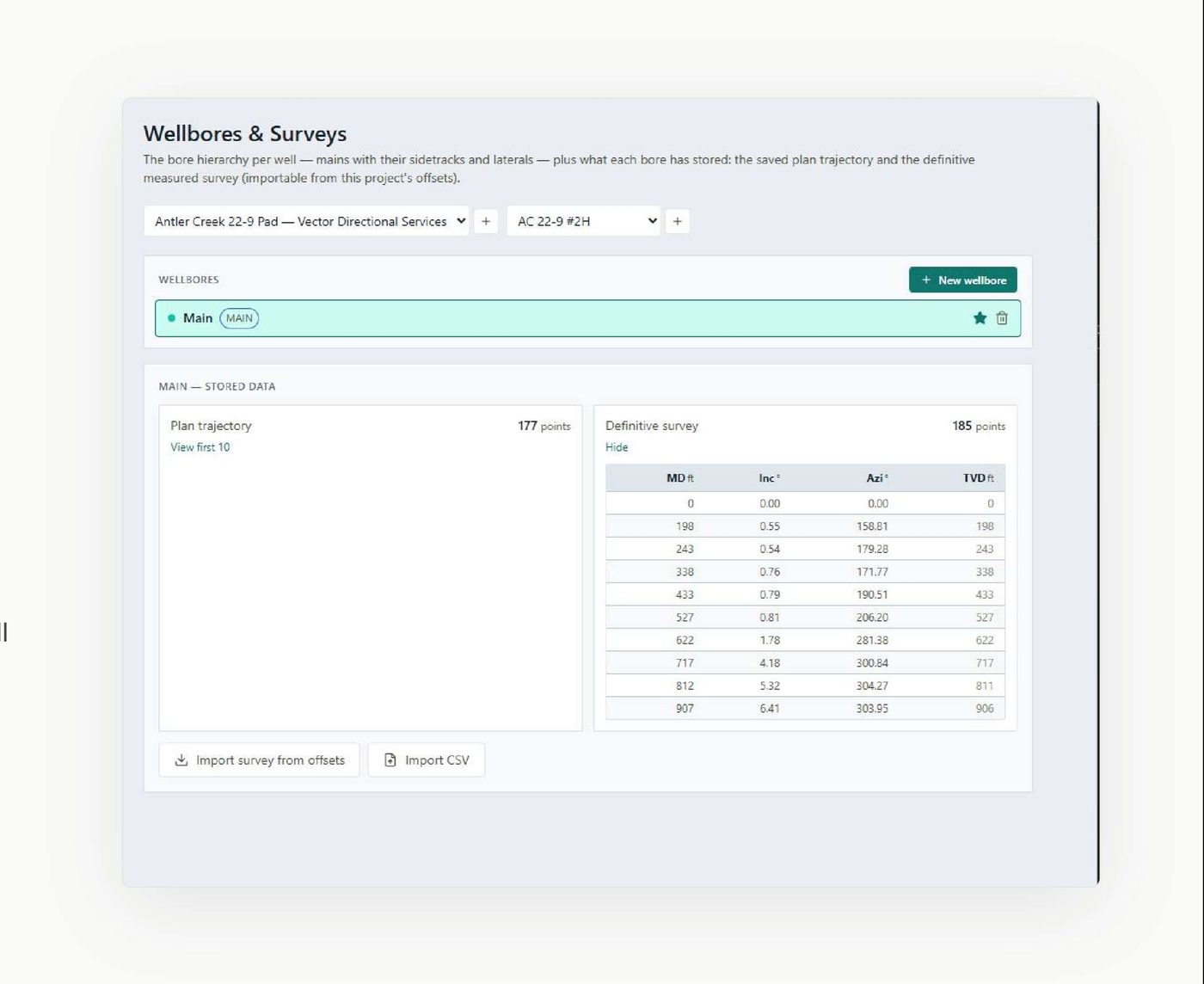
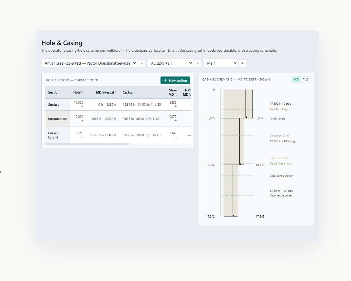
- Foundation Site, surveys, targets, formations, hole and casing, offsets.
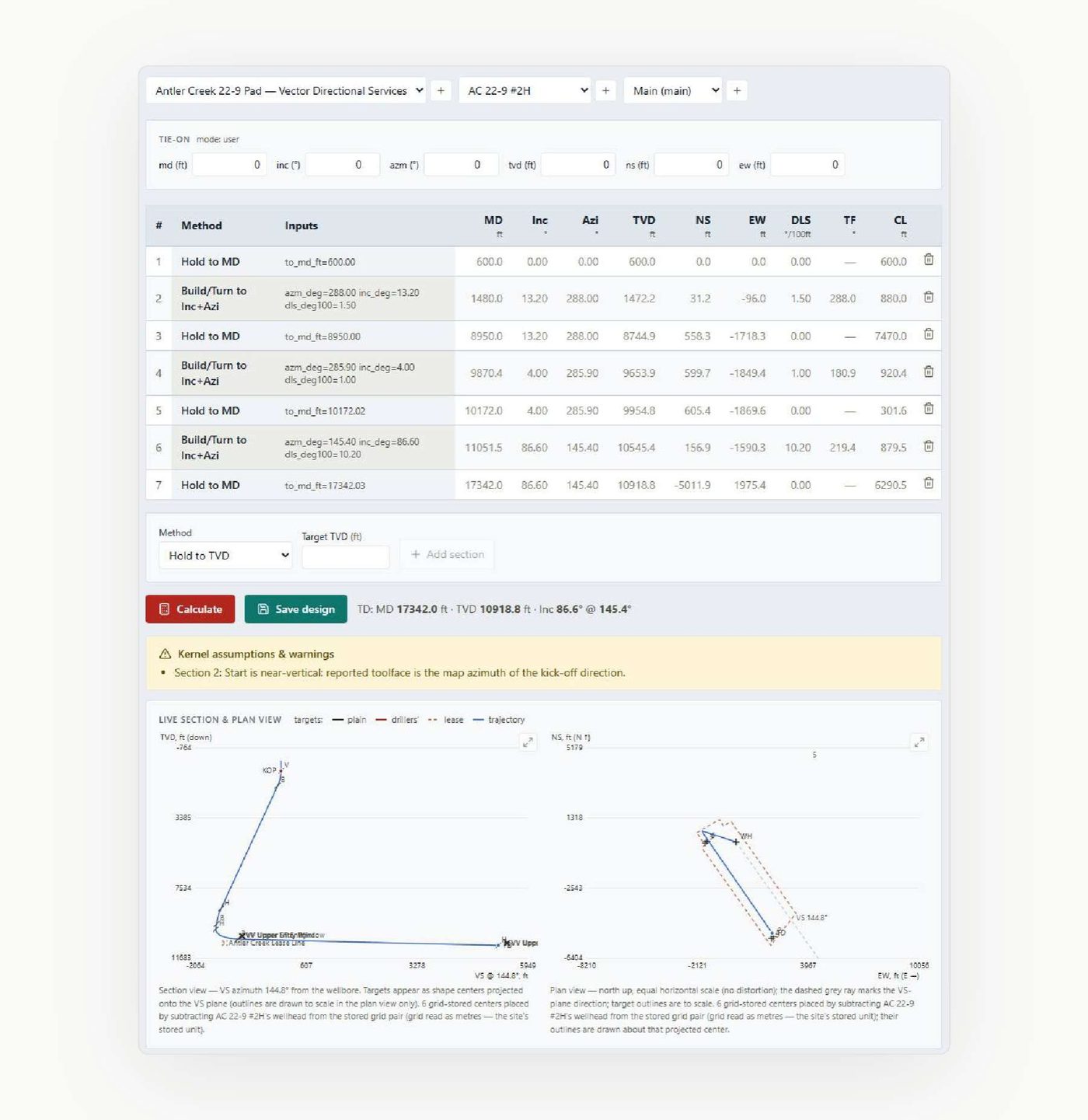
- Planning and integrity Trajectory, anti-collision, survey quality control.
- Engineering BHA and drillstring, torque and drag, hydraulics, critical speed.
- Execution Daily reports, slide sheets, pipe tally, plan versus actual.
- Deliverables Certified reports, the End-of-Well composite and the wall plot.
Foundation
The project, and what it is built on
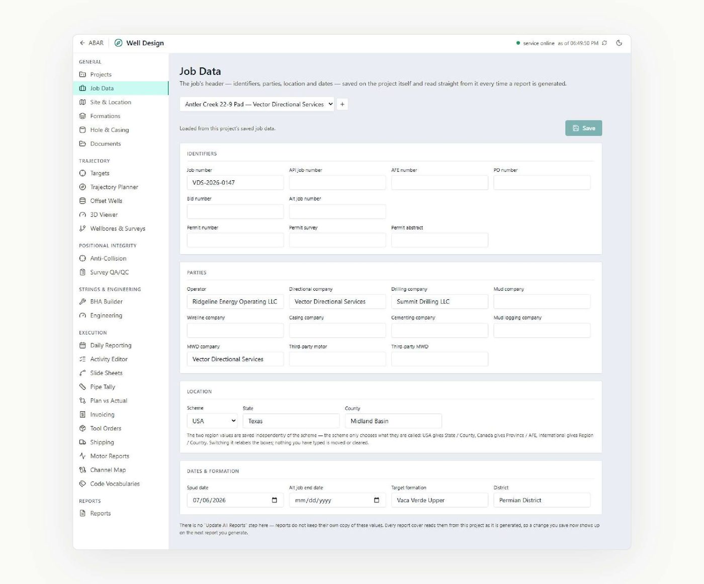
Each job is a project containing its wells and wellbores. Job identifiers, parties, location and dates are stored once and read by every report cover at generation time.
Surface locations are stored with their coordinate reference system, north reference and grid convergence. The pad layout is drawn to scale from the slot coordinates, and the site's geomagnetic reference model is computed in the application from the published IGRF model.
Foundation
What the well is made of
Positional integrity
Anti-collision scanning and analysis
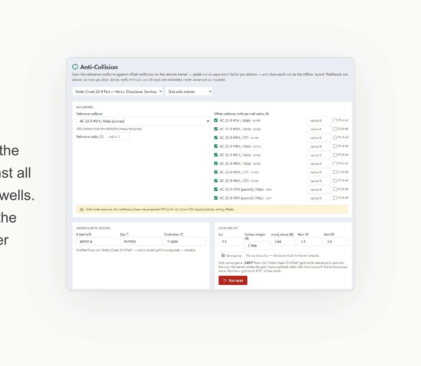
Separation-factor scanning follows the ISCWSA pedal-curve method against all selected offsets, including planned wells. Results are stored per station with the scan policy, the geomagnetic header and the trajectory source of every well, forming an auditable record of each scan.
The analysis is presented three ways: a ladder plot of separation distance against measured depth for every offset, a travelling cylinder showing offset bearings and distances around the reference wellbore, and a spider plot of the pad at any chosen true vertical depth.
Positional integrity
Survey quality control, and the wells around you
Each survey leg is checked for build rate, turn rate and dogleg consistency, with field-acceptance checks against the site's geomagnetic reference where sensor data is present. Verdicts can be written back to the survey stations, and the survey programme prints on certified reports.
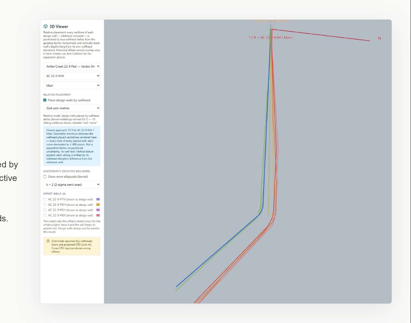
Offset wells are attached from the platform's historical daily-report database, including their surveys, or entered from imported survey files. The project's offset selection is saved and used by anti-collision scanning.
Engineering
The string, and what it will do
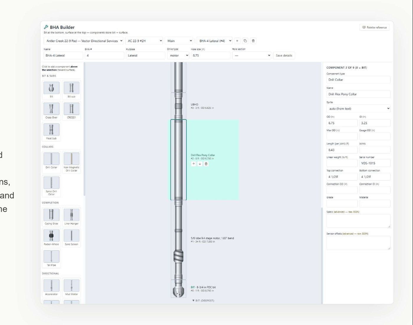
Bottom-hole assemblies are defined component by component with dimensions, weights and connections, supported by a component catalogue and import from historical runs. The same drillstring definition is used by every engineering module.
- Torque and drag. Hookload roadmaps computed across a depth range in one operation — pick-up, slack-off and rotating weights at each bit depth, with casing shoe position and friction factors per hole section. Friction sweeps and buckling screening are included.
- Hydraulics. The circulating system end to end: standpipe pressure broken down by component, ECD at the bit and shoe including cuttings loading, annular velocities, and an operating envelope covering hole-cleaning minimums, laminar limits, system volumes and lag times.
- Critical speed. Lateral vibration screening across the operating RPM range, which identifies the resonance bands before they are drilled through.
Execution
What the well actually did
Daily reports carry coded activity breakdowns, depths, mud properties and non-productive time recorded to the minute. Activity and phase codes come from configurable vocabularies, and the time distribution feeds invoicing.
Slide sheets record ordered drilling intervals with eight operation modes, toolface, and operating parameters per interval, tied to the BHA and the wall clock. Recorded motor yields are plotted against survey-derived curvature for reconciliation. Pipe tally is joint by joint with running totals and in-hole status.
Deliverables
The documents at the end of it
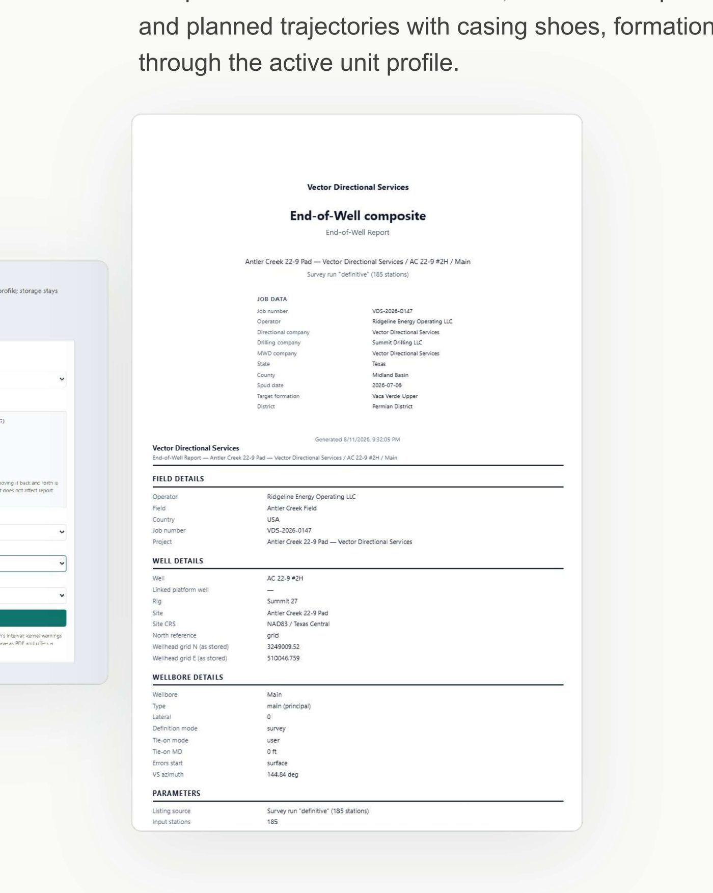
Report definitions cover plan listings, survey listings, certified reports with sign-off, anti-collision reports, error-ellipse listings and BHA sheets. The End-of-Well composite assembles the wellbore's complete record into one document, and the Wall Plot produces a landscape deliverable of the definitive and planned trajectories with casing shoes, formation tops and anti-collision results.
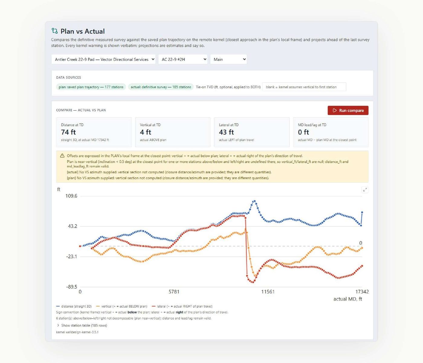
From the last survey station the engine projects the path ahead, solves the build rate required to land at a target depth and inclination, and solves two-curve profiles to a specified landing point — stating its assumptions and the engine version that produced them. Motor performance reports are prefilled from the BHA run, slide sheet and daily records, then completed for the client file.
Tool orders, shipping tickets and rate-sheet invoicing are managed alongside the engineering record, with inventory movements and line derivations handled by the platform.
Validation
Checked against real plans and real wells
The module's trajectory, anti-collision, torque-and-drag and hydraulics computations have been validated against professional directional plans and measured field data. Every stored result carries the engine version and the warnings it was produced with.
Note
Scope
Well Design works on your own well data. The screens on this page show dummy sample data.
RAK Engineering · rakengine.com/abar/well-design/ · support@rakengine.com